Analysis of Potentiometer Application Circuits Circuit Diagram We can use this circuit to control the brightness of an LED. Just connect an LED to a resistor of around 350 to 400 ohms, and then connect this to the potentiometer and use a 9 volt battery. It should look like this. When we turn the shaft we can control the current and that changes the brightness of the LED.
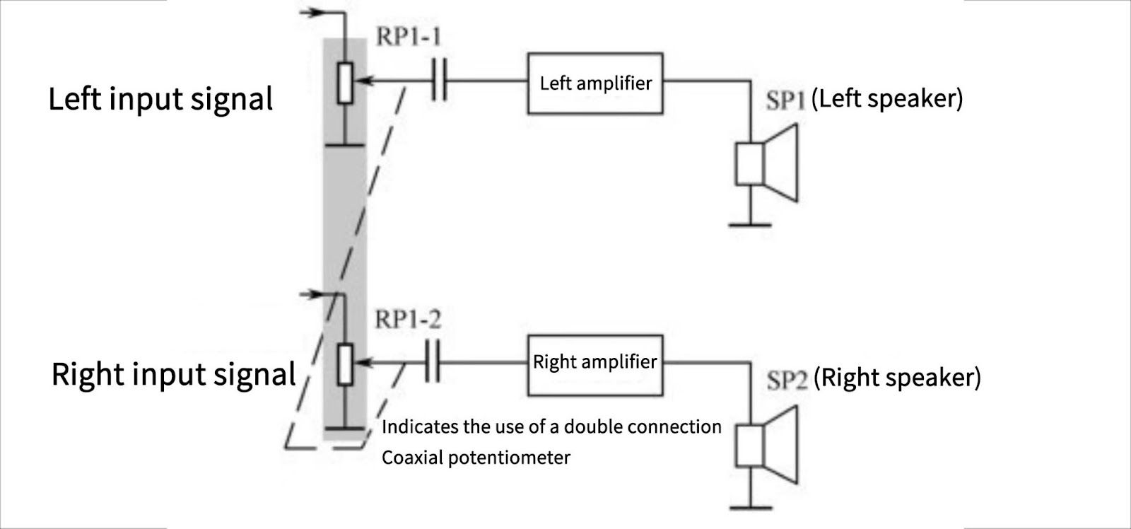
Volume Control Circuits. Devices that produce sound through speakers, such as amplifiers in audio systems and televisions, typically use this type of circuit to control the volume of the speakers. Single-Channel Volume Controller . The diagram shows a single-channel volume controller made up of a single potentiometer. In an actual circuit, it's advisable to include an additional resistor in series to safeguard the LED, even if adjusted to the point where the resistance approaches zero. Potentiometer as Volume Control. In this illustration, all three pins of the potentiometer are employed to establish an uncomplicated method for adjusting the volume of an
Potentiometer Explained Circuit Diagram
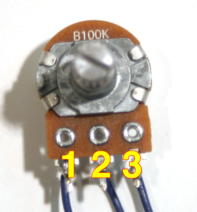
In a real circuit, Wiring Example #3: Potentiometer as Volume Control. This example uses all three pins of the potentiometer to create a simple way of adjusting the volume of an audio amplifier. By connecting it like this, you'll get a voltage divider that decreases the voltage of the input signal. The more you turn the shaft, the more The most obvious use of the potentiometer which most of us have spotted is volume control in radios and other audio equipment. type of rotary potentiometer that can be fixed once in the circuit and used to make occasional adjustments to the circuit. The rotary wiper on the POT can be adjusted by using a small bladed screwdriver or a similar Potentiometers, or pots, are a type of resistor used to control the output signal on an electronic device, like a guitar, amplifier, or speaker. They have a small shaft on top that functions like a knob; when the user turns the shaft, it turns the resistance on the signal up or down.
A volume potentiometer, also known as a volume control or pot, is a device used to adjust the volume level of audio signals in electronic devices such as amplifiers, radios, and musical instruments. It is essentially a variable resistor that allows the user to adjust the amount of current flowing through the circuit, thereby controlling the volume.

How to Wire a Potentiometer: 10 Steps (with Pictures) Circuit Diagram
To add tone control to your volume controller circuit, you can incorporate a simple RC (resistor-capacitor) filter. By using a potentiometer to vary the resistance in the filter, you can adjust the treble or bass response of the audio signal. Frequently Asked Questions (FAQ) Can I use a volume controller circuit with any audio system?
