How To Make A Simple Fire Alarm Circuit Diagram Step 5: Power up the Circuit & Adjust the Sensitivity. Working Explanation. The fire Alarm circuit working is simple here we used a 10k NTC Thermistor to detect the fire and an LM358 Operational amplifier in comparator mode. What the thermistor does is when the temperature of the room OR area increases it decreases the resistance and as we look

This FLAME sensor /fire detector uses only a IR receiver to detect Flame or fire. and there's an LED to indicate the output. No micro controller needed. Flame sensors or Fire Detectors are pretty famous in DIY world. The circuit is too easy , you can make this from the pin outs (pic2) . Connect he LED and IR diode legs as shown in picture 3 The working and design of a Fire alarm circuit using LM358 is quite simple. LM358 is a dual-operational amplifier. In this project, this IC operates in Comparator mode. The input signals are applied to the inverting terminal whereas non-inverting terminals are compared and the output is produced.

How to make a Fire Alarm Circuit using 555 timer Circuit Diagram
Circuit 5 Fire Alarm Circuit Using Germanium Diode. This is a simple fire alarm circuit using Germanium Diode and 555 timer. In this circuit Germanium Diode play very important role in detecting the fire. This circuit is very easy to construct, cost effective and implementable. Block Diagram of Fire Alarm Circuit Using Germanium Diode

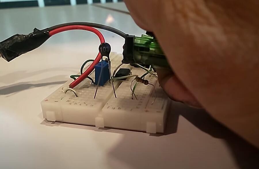
In this project, we will make a simple fire detector alarm circuit using BC547 transistor and IR detector LED on Breadboard. This circuit can easily detect any fire nearby and accordingly start the buzzer. Circuit Diagram of Fire Detector: Component List: 1. BC547 Transistor (NPN) 1no 2. Infrared Receiver LED 1no 3. 220-ohm Resistor 1no 4

How to make a Simple Fire Detector Alarm Circuit Circuit Diagram
In this video i will shown, how to make fire detector alarm circuit at home, using bc547 and Infrared Receiver.easy to make fire detector alarm at office e