OMEGA Circuit Diagram Below is a comprehensive guide to the top 10 MOSFET manufacturers in the world, celebrated for their technological innovation, robust product lines, and contributions to global industries. Whether it's ultra-low power consumption or high-power density, these companies lead the charge in shaping the future of electronics. Part Number: BS170 Datasheet Link: BS170 MOSFET Datasheet link Similar Products: BS170F BS250. BS250 is a P-channel enhancement mode MOSFET in a TO-92 package, and it is designed to work with low voltage and low current applications. Listed below are some basic features of BS250 MOSFET which make it suitable for certain applications:. It has a low threshold voltage of -1.9V which means it can Conclusion: VD technology is a mature and reliable solution that combines simplicity and versatility, making it a frequent choice for moderate power applications. Super Junction (SJ) Technology: 500V-1050V. Super Junction technology represents a significant advancement in MOSFET efficiency by introducing a multilayer structure with alternating P- and N-type regions.
MOSFETs, or Metal-Oxide-Semiconductor Field-Effect Transistors, are essential components in power electronics, used in everything from switches and amplifiers to energy converters. Choosing the right MOSFET facilitates bidirectional results in high performance and efficiency, especially in electronic systems with stringent power and efficiency requirements. MOSFETs are some of the most important components involved in stable power delivery, fast switching, and low loss in a range of applications. In particular, discrete MOSFETs enjoy a primary role in motor control, power regulation, specialty logic, high power amplifiers, lighting, and other systems requiring high current draw with low loss. A Power MOSFET is a specialized MOSFET designed for high power applications. It offers fast switching speeds and superior performance at low voltages compared to standard MOSFETs. Its fundamental operating principle remains the same as that of general MOSFETs. The most common types are n-channel Enhancement-mode, p-channel Enhancement-mode, and n-channel…

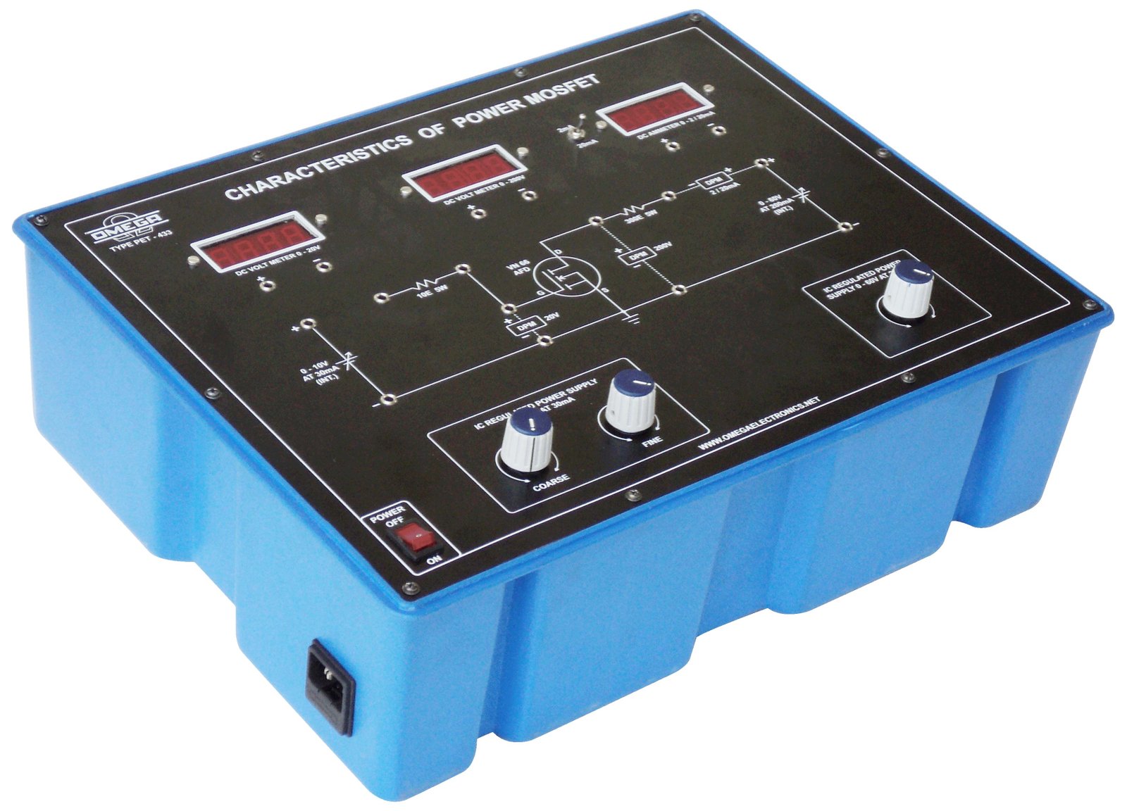
Selecting the Right MOSFET for High Circuit Diagram
Power MOSFETs are the most common low-voltage (less than 200 V) switch in use, and can be found in power supplies, DC-DC converters, and controllers. Operating Principles and Specifications. Like all MOSFETs, power MOSFETs switch and regulate a current that flows between the source (S) and drain (contacts) by varying voltage at the gate (G When designing high-power electronics such as electric vehicle (EV) inverters, power supplies, or motor drives, choosing the right MOSFET is critical. Engineers must balance efficiency, thermal performance, switching speed, and cost to optimize the design. This article dives into the trade-offs between silicon (Si), silicon carbide (SiC), and gallium nitride (GaN) MOSFETs and provides

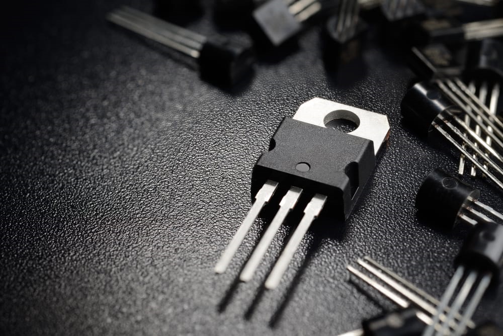
The BOJACK IRFZ44N MOSFET Transistor TO-220 is a pack of 20 N-channel rectifier power MOSFET transistors that can handle a maximum drain current of 49A and voltage Vds of 55V. With a power of 83W, this transistor is ideal for a variety of MOSFET transistor applications.