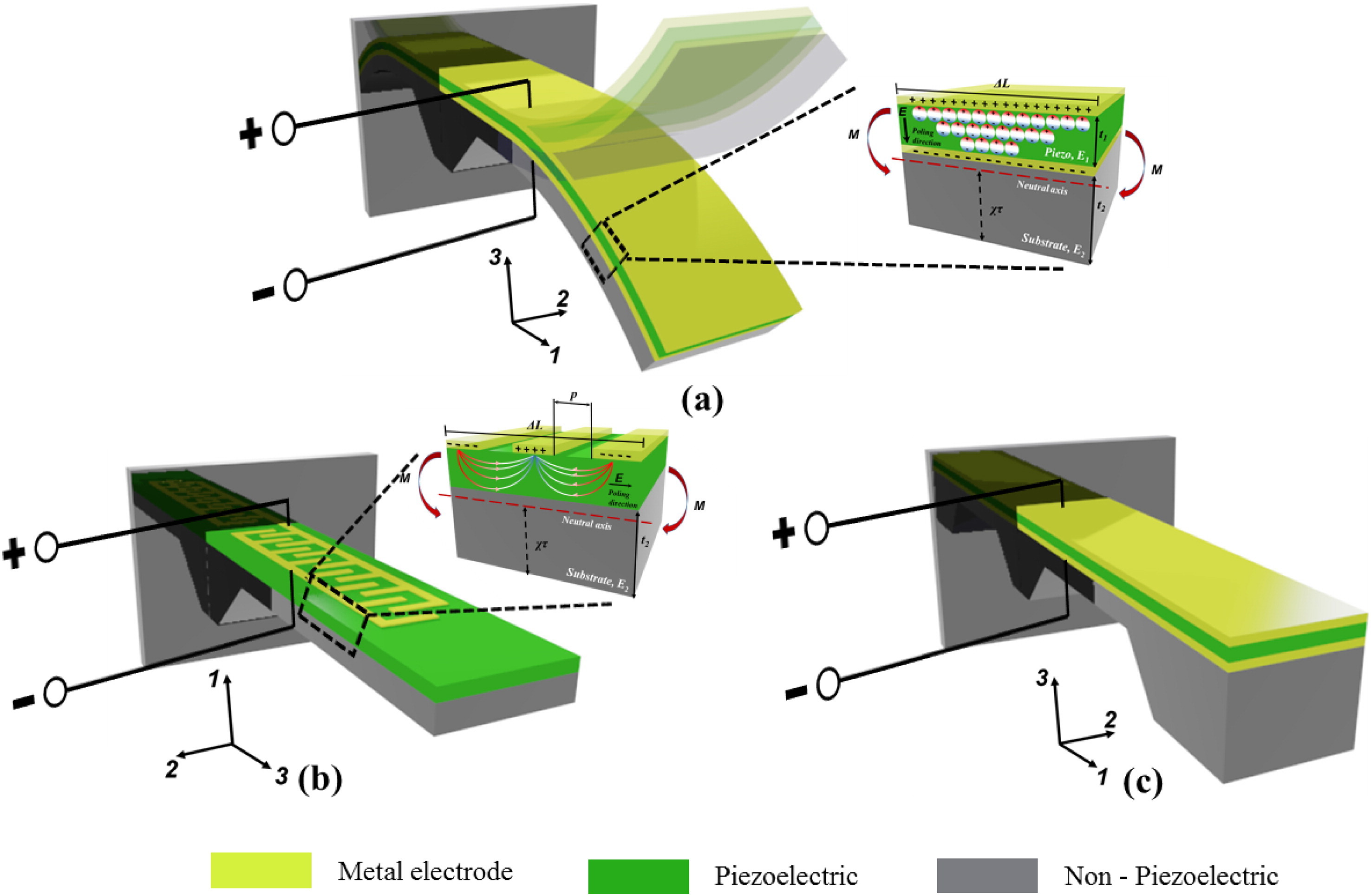
Piezoelectric Energy Harvester Designs Circuit Diagram A hybrid energy harvesting scheme and system integrating radio frequency (RF) electromagnetic wave and solar energy based on optically transparent metasurface is proposed and constructed for the first time in this article. The scheme combines the RF link and the solar link through the high-efficiency transparent metasurface and rectifier circuit, the solar cell, and the power management Hybrid energy harvesting systems are widely combined with various sensors to form intelligent systems due to their efficient energy harvesting and sensing performance. Feng et al. integrated a hybrid energy harvesting device, power management circuit, sensor, microcontroller, and wireless communication module to create an intelligent ocean buoy The rectification of the piezoelectric system along with its results is discussed. Different circuits for amplification is studied and simulated to improve the voltage. All the practical experimental outputs and the different software used to gain these outputs are recorded. The various applications of the hybrid system are reviewed and discussed.
Irrespective of using individual energy harvesting devices to scavenge one particular energy source at a time, designing a hybrid device that can convert multiple energy sources simultaneously would be a more rewarding approach to improve power outputs [8], [9]. In addition to improving power efficiencies, it is also noted that mechanical
Research on Hybrid Energy Collection Methods Applied to ... Circuit Diagram
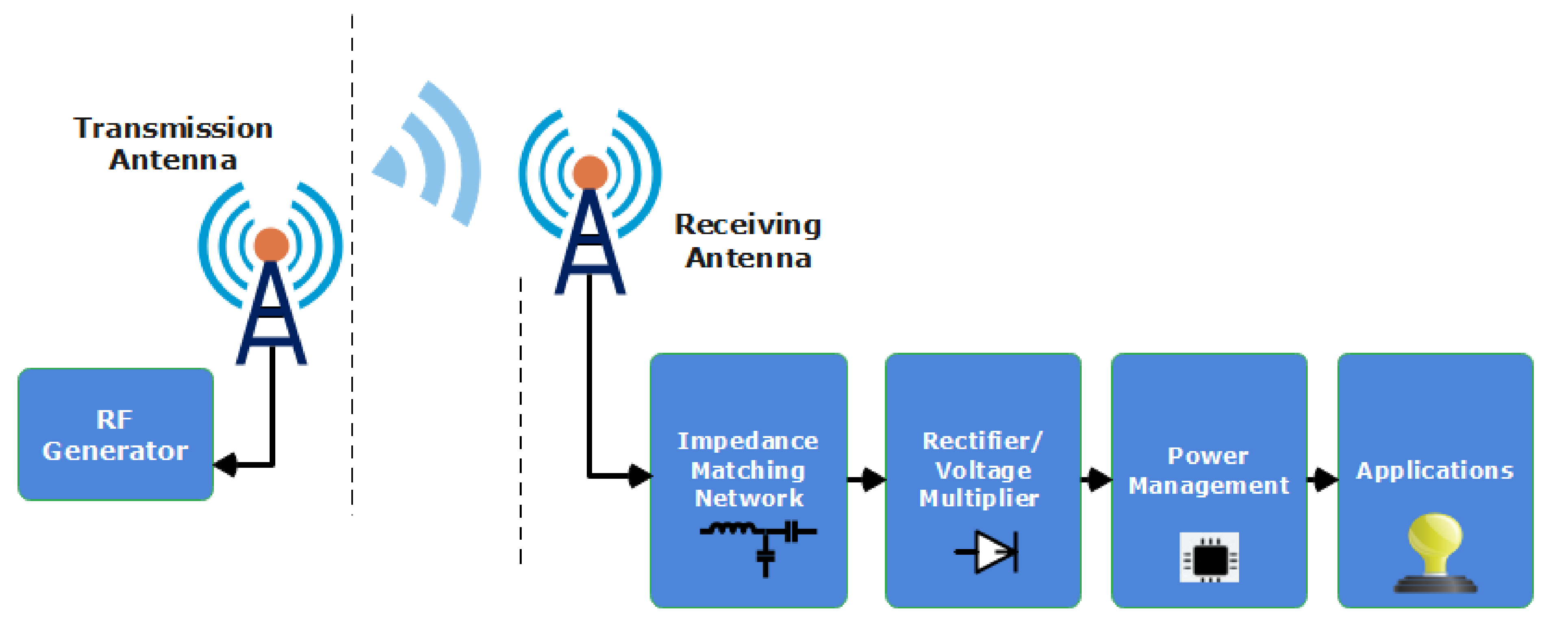
Power management circuit design is another critical challenge for hybrid energy harvesting. Outputs in alternating current form are typical for piezoelectric and electromagnetic harvesters. Rectification, energy storage and voltage stabilization are necessary to accumulate collected charges on a single storage.
In today's research landscape focused on efficient energy utilization [2, 3], nanogenerators (NGs) and supercapacitors play pivotal roles in harvesting energy from microenergy sources [4, 5].However, the unpredictability of these sources challenges device reliability, prompting exploration into hybrid solutions that can harness energy from multiple sources simultaneously or intermittently. This paper presents a comprehensive exploration of a Hybrid Energy Harvesting System designed to harvest energy from diverse sources, including 2.4 GHz and 5.8 GHz RF energy, electromagnetic (EM) energy, solar energy, and triboelectric energy. The proposed converter operates within a wide input voltage range, maximizing efficiency and stability. A reconfigurable RF-DC converter is used for

From Triboelectric Nanogenerator to Hybrid Energy Harvesters: A Review ... Circuit Diagram
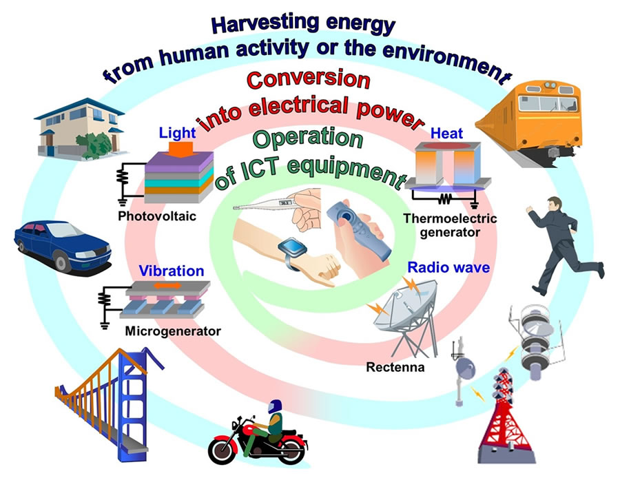
To further enhance the energy-harvesting performance of TENG, hybrid energy energy which was measured as an open-circuit voltage (dimension: 3 × 3 × 0.025 cm; dielectric constant: 3800 V/m in wireless sensor networks). As traditional energy sources continue to deplete the cost of their utilization continues to increase. This fact has generated a growing interest in energy harvesting on a global level. Figure 1 illustrates how a simple energy harvesting scheme is employed to convert and store ambient energy into electrical energy.
