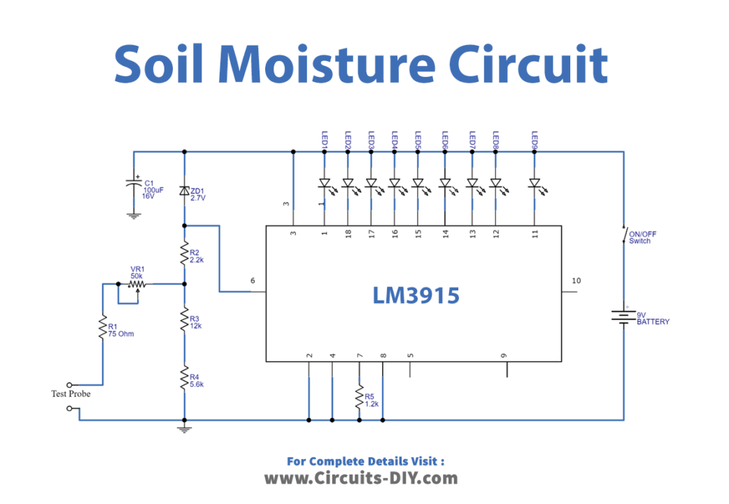
Soil Moisture Sensing Circuit Circuit Diagram The soil moisture sensor, also known as the soil humidity sensor, features four pins: VCC, GND, Aout, and Dout. These pins facilitate the retrieval of soil moisture data from the sensor: VCC: Power supply pin, connectable to either 3.3V or 5V supply. Note that the analog output varies depending on the supplied voltage. In this project, we will build an automatic plant watering system using a soil moisture sensor and Arduino. The soil moisture sensor will be used to measure the moisture level in the soil and the Arduino will be used to control the watering system. Required material. Arduino Nano* 1; Soil Moisture sensor * 1; 5v relay module * 1
The soil moisture sensor is the first thing that springs to mind when it comes to building your smart irrigation system or automatic plant watering system.With this sensor in place and a little Arduino support, we can design an automatic irrigation system using arduino that can water your plants when it's needed, avoiding overwatering and underwatering.
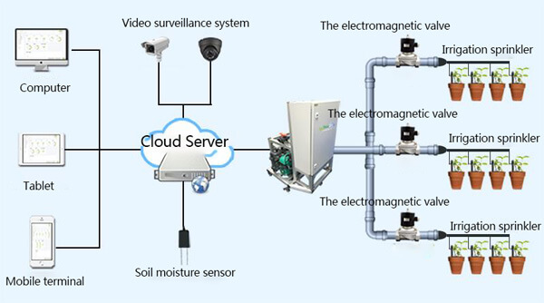
IoT based Smart Irrigation System using Soil Moisture Sensor and ... Circuit Diagram
The process of this irrigation system. Insert the soil moisture sensor probe into the soil while the system is operating. The moisture content will then be displayed on the LCD as Low, Medium, or High. The relay module will automatically activate when the moisture level is LOW and deactivate when it is MEDIUM or HIGH.

Referring to the given schematic we see a simple yet highly accurate soil moisture sensor circuit with an automatic preset water shower system for restoring the soil moisture level to optimum points. The design is based on a single voltage sensor/LED driver IC LM3914 or a LM3915. The shown sensor pins which are basically two brass rods are One way is to build an electronic soil moisture sensor. This project will show you how to build a circuit that indicates whether soil is wet or dry, but the circuit itself is unprotected. It will be up to you to engineer a solution, like a waterproof carrying case that turns the basic circuit into a useful, portable soil moisture sensor. It's easy to hook up with your garden irrigation system or build your controller. The sensor is based on two resistors that create a voltage divider circuit when wired together in series. This soil moisture sensor circuit uses a single transistor and 4 LEDs to indicate the soil moisture level. The transistor is used as a switch to light up
How to make an automatic irrigation and plant watering system using ... Circuit Diagram
We are going to dive into the world of soil moisture sensors. I'll show you how they work, the different types, and how to assemble them with Arduino. Plus, we'll build two amazing projects together to exercise what we have been learning so far. The Soil moisture sensor is used to sense the moisture levels of the plant soil. This sensor senses the soil moisture levels and produces output. When the Arduino detected the low moisture level in the soil by the sensor, then the Arduino gives the signal to the Relay module to turn on the Pump for automatically watering the plant.

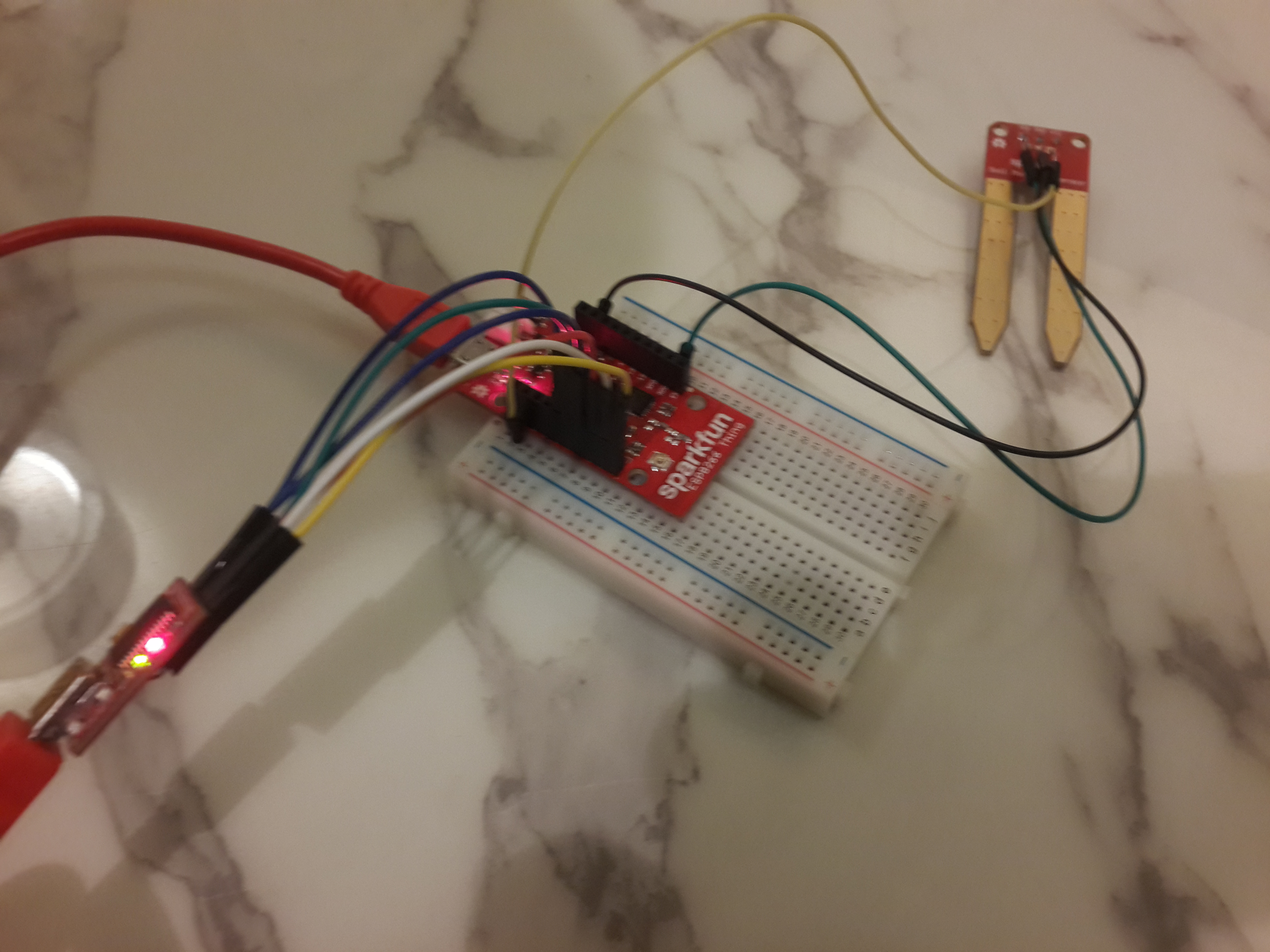
Here we build a IoT based Irrigation System using ESP8266 NodeMCU Module and DHT11 Sensor. It will not only automatically irrigate the water based on the moisture level in the soil but also send the Data to ThingSpeak Server to keep track of the land condition.
