Sound Detection Sensor Module Internal Circuit Diagram A sound sensor works by capturing sound waves through a microphone and converting them into electrical signals. When sound waves hit the microphone diaphragm, they create variations in air pressure. These variations are translated into electrical signals, which are then amplified by an onboard amplifier circuit.

A simple sound sensor circuit made from few components, with mic to pickup the sound.Heartbreaking by Kevin MacLeod is licensed under a Creative Commons Attr 🔊 Make an Alarm with UM66! Simple Sound Circuit TutorialLooking for an easy way to generate sound or build an alarm using a simple IC? In this video, I'll s In today's video I want to show you how to make simple sound sensor circuit using micro.-----
Arduino Tutorial - Arduino Getting Started Circuit Diagram
Making a simple sound sensor circuit requires a few basic components: an amplifier, a microphone, and an output device. First, the microphone should be connected to the amplifier to amplify any incoming sound waves. The output of the amplifier can then be connected to the input of the desired output device (such as an LED or speaker) which will The sound sensor is capable of detecting the presence of sound in the surrounding environment. It can be used to create sound-reactive projects, such as clap-activated lights or a sound-activated pet feeder. In this tutorial, we are going to learn how to use Arduino and sound sensor to detect the sound. In detail, we will learn: Common Issues and Solutions. If your Arduino Sound Sensor isn't working, try this: LED not responding: Ensure the LED is correctly placed according to its polarity and that all connections are secure.; No reaction to sound: Adjust the sensitivity of the sound sensor, if possible, or check the connections to pin 2.; Conclusion. You now have a sound-activated LED switch!
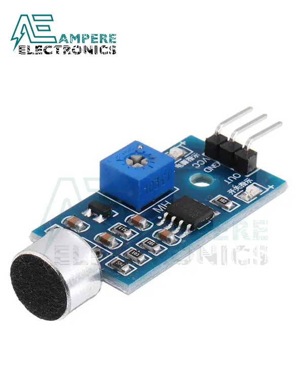
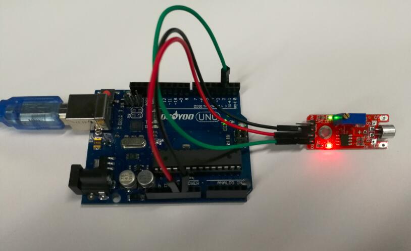
A sound sensor switch is a type of switching device that responds to an audio input. With a proper sound-activated switch, dynamic control by sound may be very useful, not just on robotic systems but also for home automation, for example, a sound-activated light responding to a knock on the door or a hand clap.So, in this project, we will build a simple sound sensor switch using the LM393N Sound Sensor Pinout. The Sound sensor module has 4 pins VCC, GND, Digital Out, and Analog Out. We can either use the AO pin as an output for analog reading or the DO pin as an output for digital readout. The Sound sensor pinout is as follows: VCC is the power supply pin of the Sound Sensor that can be connected to 3.3V or 5V of the supply. But
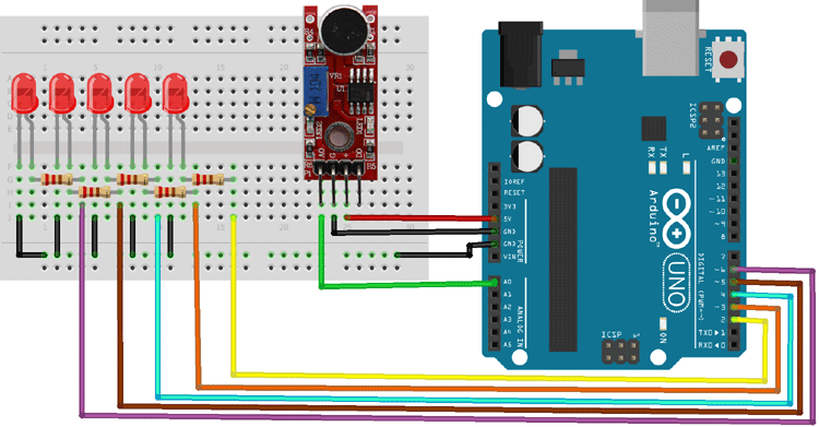
Sound Sensor with Arduino Tutorial Circuit Diagram
This easy to build circuit will let you detect sound with your ARDUINO, You can buy a pre made sound detection sensor module but they don't work worth a sh!t from my experience. The picture above shows you the simple circuit design, just build that and it will work better than most of the pre maid modules you can buy. PARTS LIST: 2 - 10kΩ